This page documents my adventures with the Quantronix Q-Mark Osprey industrial laser. While I do have a reasonable budget for my laser hobby, I have nowhere near the funding required to buy much of any of this stuff new. Thus, my laser adventures involve discount used parts and broken items for repair. It turned out to be quite an adventure putting everything together to make the laser engraving system described here. Finding used parts as well as information and documentation for the parts was a fun first step, and the repair and final assembly of the equipment was full of wonderfully-fun ups and downs.
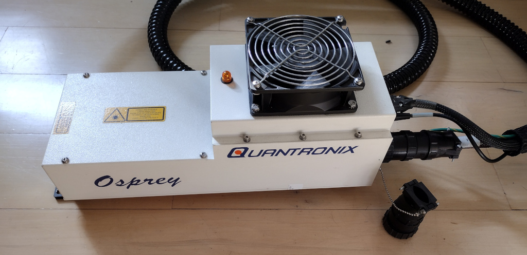
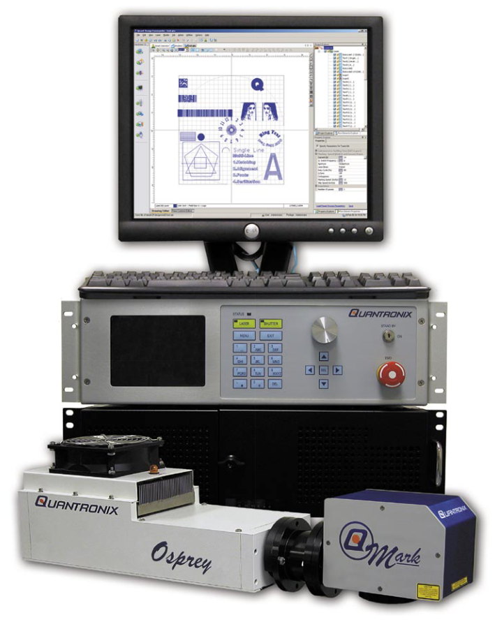
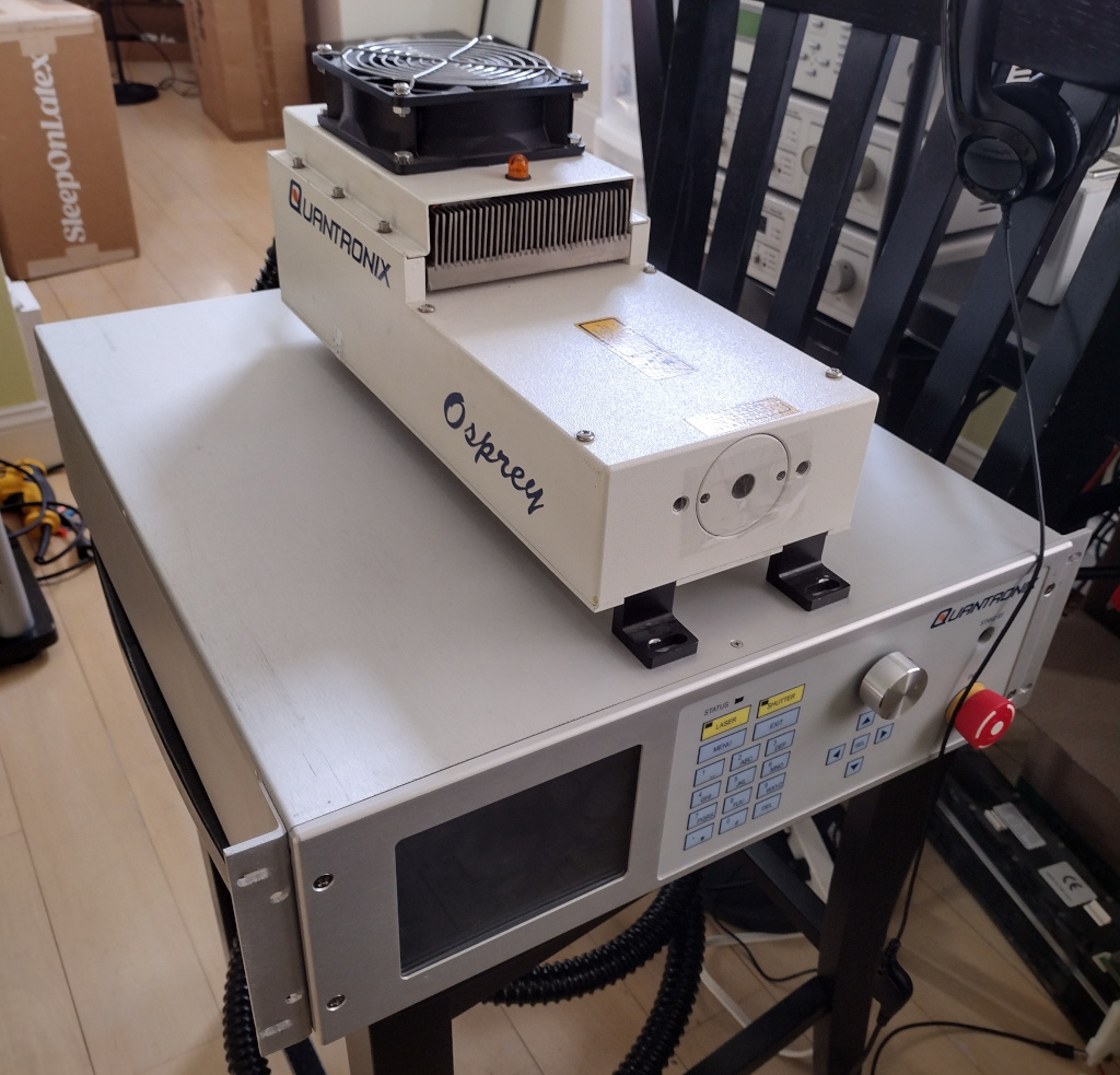
While I’m sure these lasers have found their way into more than one application, the original purpose was for laser engraving / marking, and the Osprey laser was sold with an attached galvanometer scan head. There isn’t much remaining information on this laser available online. While it might be possible for one to dig up more than I’ve seen with a few hours of Google searches, about the only thing readily available is a two-page sales document in PDF format. I’ve archived a copy of the PDF document on my site, available with the following link Qmark-Osprey.pdf. This PDF gives a basic description along with a couple of pictures; the pictures, which include a shot of the power supply unit (PSU) / controller, turned out to be very important as will be discussed later. A screen capture from the PDF showing a complete system is included below, followed by a photo of the system I have.
The 1064-20-L Q-Mark Osprey’s technical data follows in the table below; I’ve omitted information on the attached scan head, as the unit I purchased didn’t come with one.
| Model: | 1064-20-L |
| Wavelength (nm): | 1064 |
| Output Power (W): | 20 (CW) |
| Pulse Width (ns): | (Typical) 25 |
| Maximum Repetition Rate (kHz): | 130 |
| Mode Type: | Low order mode |
| Beam Quality (M2): | M2 < 1.4 |
| Power Stability (%RMS): | 2.0 |
| Beam Pointing Stability (μrad): | 30 |
| Electrical Service: | Single Phase 100-264 VAC, 50/60 Hz |
| Laser Power Consumption (W): | 800 (Typical) |
| Cooling: | Air-Cooled |
| Operating Temperature Range (°C): | 15-35 |
| Relative Humidity (%): | 8-80, non-condensing |
Some features listed in the PDF follow:
I’ve never been able to find any information on the Design Commander software the PDF talks about and certainly haven’t been able to find a copy of it anywhere. Luckily, the laser I acquired didn’t come with a scan head anyway, and the laser can be turned on without any external software.
Quantronix Inc. was initially founded partly by Dr. Richard Daly. He was deeply involved in the early days of laser research and development and participated in the race for the creation of the very first laser in history. I personally recommend obtaining and reading a copy of “Beam: The Race to Make The Laser”: by Jeff Hecht for detailed coverage on the race to the development of the first lasers ever created in history. The obituary of Dr. Daly from the the New York Times is included below, published on November 11th 1989 in the New York Times.
“Richard T. Daly, a nuclear physicist who helped develop the first commercial laser, died of cancer on Nov. 3 at Massachusetts General Hospital in Boston. He was 64 years old and lived in Castine, Me. -- Dr. Daly was chairman and co-founder of the Long Island-based Quantronix Corporation, a manufacturer of lasers for industrial, scientific and medical uses. He retired in 1987. He is survived by his wife, Genevieve; two sons, Robert and Richard, both of Boston; a daughter, Catherine Mossholder of Huntington, Beach, Calif.; his mother, Annette Wulman, and a sister, Deborah Bohlen, both of Portsmouth, Va., and a brother, John, of Holland, Mich.”
The Quantronix company has been out of business / acquired for quite some time as of this writing (2023-2024). Reddit user yaumamkichampion commented in a post in r/AskElectronics in 2023 that “Quantronix was consumed by Continuum, and Continuum was consumed by Amplitude.” Replies from other users there seem to agree. However, when one searches for Quantronix on Google, there’s some information available which seems to indicate a link with Cubiscan. Their website https://cubiscan.com/company/ appears to be relevant. A copy of some of this text follows.
“The development of an automated cubing (dimension scanning) and weighing system first began with a need at U.S. Department of Defense supply depots in the mid-1980s. Their receipt of goods from vendors and inter-organization shipments required that military shipment labels disclose parcel dimensions and weight. Furthermore, they needed item cube data to optimize the use of storage space at supply depots. Prior to the development of an automated solution, their only option was to measure product with tape measures and scales, recording all results manually. The process was time-consuming and error-prone. To address these issues, the founder of Quantronix set out to develop a more effective and efficient product solution.
By 1987, a prototype had been developed and in early 1988, an equipment demonstration was arranged with the U.S. Department of Defense. There, officials had an opportunity to see the potential solution, ask questions, and test a product prototype. The initial response was positive, and in 1989, Quantronix was designated a prime contractor for the U.S. Defense Logistics Agency. A large quantity of dimension scanning systems (model Cubiscan 100) were then installed.
In 1990, Quantronix began to pursue private-industry needs for automated dimensioning systems, both in transportation and distribution industry applications. By mid-1990, the company had established itself as an innovative supplier of stationary and in-motion cubing systems, capturing contracts with large courier and logistics companies in both the U.S. and Canada.
Today, Cubiscan is the global leader in dimensioning with thousands of installations at many of the world’s largest companies.”
Some other sites appear to support the above description. For example, https://www.cbinsights.com/company/quantronix lists Quantronix as acquired and provides some additional information:
About Quantronix: Provider of lasers.
Founded Year: 1967
Stage: Acquired
Headquarters Location:
49 Wireless Blvd
Smithtown, New York, 11787,
United States
(516) 273-6900
The following patent listed on the CBINSIGHTS site does fit well with the description from Cubiscan’s page:
Application Date: 12/22/2014
Grant Date: 2/28/2017
Title: Object dimensioning system and related methods
Status: Grant
However, https://pitchbook.com/profiles/company/131133-52#overview seems to show a different date for the founding of the company (1987) than CBINSIGHTS (1967). Perhaps the ‘67 was a typo as Cubiscan’s page does mention “the mid-1980s.”
A previous employee provides some information on the https://www.indeed.com/cmp/Quantronix-Inc website about working for Quantronix as an Electro-Mechanical Technician in East Setauket, NY, where he writes:
“Quantronix was a world-wide leader in laser manufacturing. We made laser systems for medical and scientific research, as well as for industrial applications. We only had about 75 employees at our particular facility, yet we were able to built an impressive number of laser systems in our various product lines.”
The address on the stickers on the back of my laser head and controller list an address that matches the city and state provided by the technician commenting on Ineed.
Quantronix Corp
41 Research Way
East Setauket, NY 11733
While I can’t say much with any authority on what exactly has happened to the Quantronix company, I hope some of the information provided above is relevant and at least interesting.
I had been spending some time poking around on eBay looking for used lasers which I might be able to refurbish. I got started looking for broken lasers which I could strip down for parts. Many of my searches would be “laser head for parts” or similar terms. I did have some luck buying various lasers, stripping out all the crystals and optical components, and reselling them. Not that I made much money doing this, and it certainly wasn’t worth my time from a financial perspective, but I was having fun taking these apart and seeing how everything was constructed. It’s a great hobby. : )
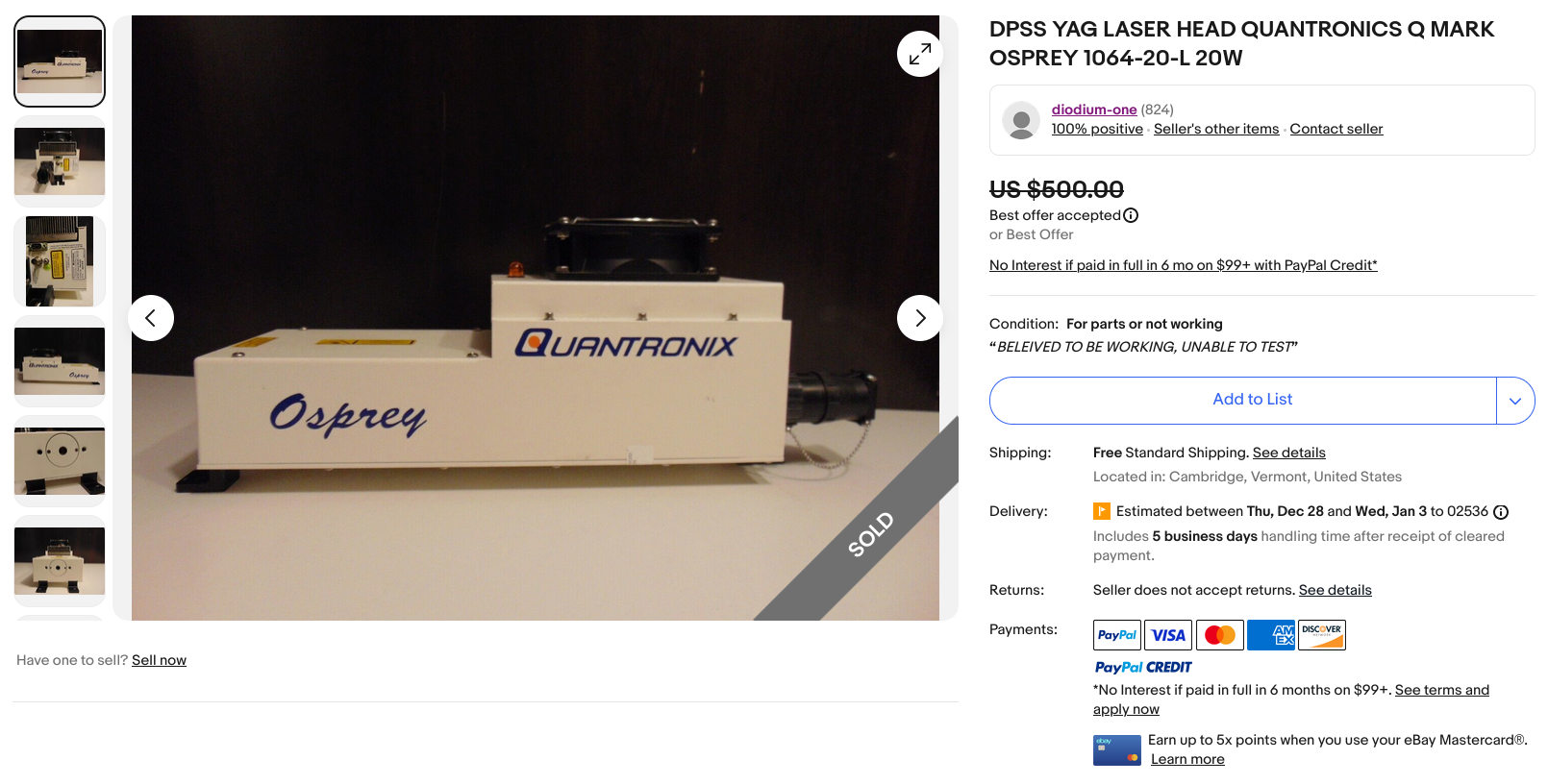
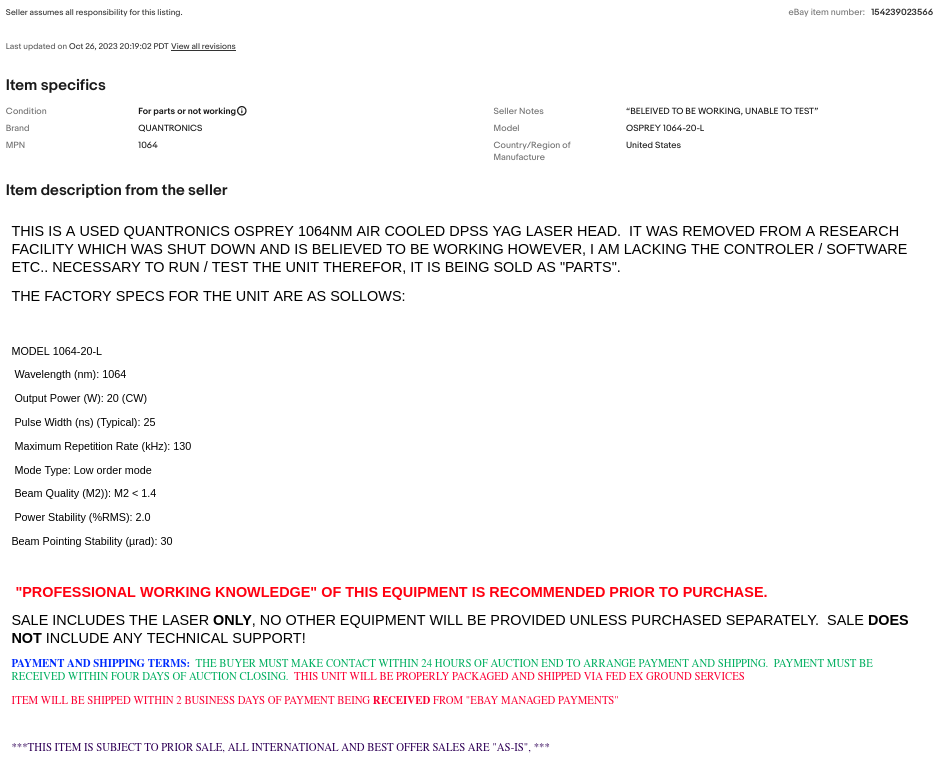
One day, a result turned up on eBay for a “DPSS YAG LASER HEAD QUANTRONICS Q MARK OSPREY 1064-20-L 20W”. Yes, the “Quantronics” typo was in the listing title. This was listed “for parts” at $500, which would have been quite the gable to make. If it didn’t function at all, I might not have been able to recover the full $500 selling the parts (though, it might have been possible). I used eBay’s “or best offer” feature and managed to negotiate a price of $325 for the unit including free shipping. This was honestly a pretty reasonable price, even if the laser wasn’t working at all. The seller did mention that they thought it was likely functional, but one always has to take that kind of eBay description with a pound or two of salt. The listing for the laser is included in the following images.
Of course, when this arrived, I had no way at all to test it because I lacked any means to power it. While it could have been possible to open things up and get out a multi-meter to see how things were wired, I lacked all the information that would have made this process a reasonable effort. Completely reverse-engineering the thing and creating a suitable driver from scratch is much more than I was willing to put into this project. Thus began the search for a compatible PSU.
Having acquired the laser head itself, the next task was to track down a compatible driver. Google searches were getting me nowhere, and I was about to give up and strip the laser down for parts when I found a listing on eBay with the title “QUANTRONIX 300-20 M023360 Control / Power Supply Laser.” Now, I had no way to be sure this model was compatible with my laser. I wasn’t able to find much information on the Q-Mark Osprey laser in the first place, let alone what the compatible controller versions were. However, I did luck out. Remember the PDF sales document I talked about above? That document didn’t list the part number or name of the controller, but it did have a picture of the thing. And better still, the picture from the listing looked pretty darn similar. I mean, if it kinda looks the same, it must be compatible, right? ; ) A screen capture of the eBay listing for the PSU follows.
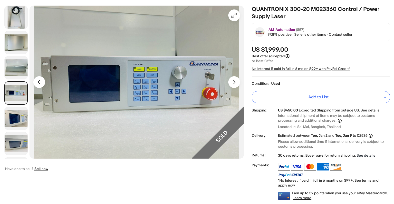
As you can see, the description is essentially empty. However, the seller did importantly offer free returns within 30-days if the item didn’t work. Now, would they accept a return if it wasn’t compatible? Perhaps not. However, I was sure I would at least get a working controller of some version, so could probably resell it if I couldn’t return it. In this case, the PSU was listed at $1,900 + $450 shipping from Sai Mai, Bangkok, Thailand. Now this was way out of my price range, but it would at least work, right? Worst case I could resell it and hopefully get all my money back. So, I went for it and offered $1000. To my surprise, the seller was willing to accept my offer of half their asking price. This was a huge help, even though the total price with shipping and tax was still ~$1,500.
After many rounds of DHL not delivering the package on time, they finally did deliver the item (though, they did not get my signature, which they should have done). I was so excited to get my hands on this thing and connect it to my laser to see if everything would work. To my dismay, the PSU wouldn’t even power on! The fans would come on, but the screen was completely blank, and none of the buttons worked. So, I went off to contact the seller and see if I could exchange it for a different one, which I was pretty sure they didn’t have anyway. The seller got back to me and said that they had no similar model in stock, and they would instead refund me the full purchase price. In addition, they didn’t want to have to pay for return shipping or have the hassle of even dealing with it, so they said I could just keep the broken unit. Wow! It was like winning the lottery. $1500 saved, and all that would be needed was to figure out what was wrong with the thing!
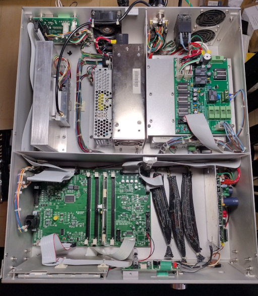
This part of the journey turned out to be a whole heck of a lot of fun. : ) After opening up the PSU, a first glance showed this thing was in excellent condition. There wasn’t a speck of dust inside; it looked totally brand new. It was easy to see that only the 24V rail on the power distribution board was live as there were some indicator LEDs for the various rails. But why? I was able to poke around with a multi-meter and see that the AC neutral and live connections to the power distribution board were good, and all the fuses were fine. So what next? My first thought was to take out one of the power supplies from inside the controller and test it independently. There were three easily identifiable power supplies: a 24V power supply, a 15V power supply, and the laser diode power supply. These are shown in the image below and are labeled in the image following it.
 (Large Version)
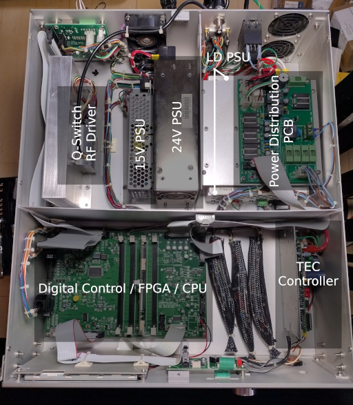 (Large Version)
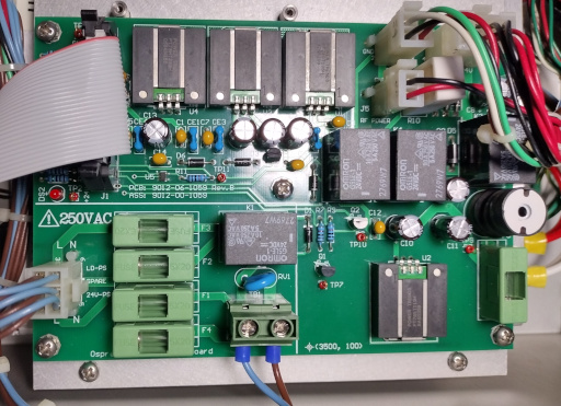
The easiest of the three power supplies to get to in the controller was the 15V supply, so I removed it and connected it directly to AC power, and it seemed to put out 15V just fine. I was confused by this, because it wasn’t powered on at all when installed into the controller. Perhaps there was a faulty connection to live and neutral? Looking into the controller case again, I could buzz out some connections to the 15V power supply. They were good and came from the power distribution board, connected directly to a fuse. The fuse was fine, so this left me thinking something must be wrong with the power distribution board itself. So, I began a more focused search there. An image of the power distribution board follows.
 (Large Version)
I could easily see that the live and neutral connections to the 15V power supply were enabled by a relay. Apparently, the power distribution board would always supply live and neutral AC to the 24V power supply, but was not turning on the relays connected to the other power supplies. At first I thought this could be an issue with the relays themselves, so I connected a lab power supply to each of the relays to test them out. They were all Omron model G5LE 24V relays. A datasheet was found online, so it wasn’t too hard to get them connected to an external power supply. I’d turn the current limit on the lab bench power supply up from zero slowly until I heard the relays click on, then turn the supply off and wait for the relays to click back off. All of them seemed fine. If it wasn’t the relays, what else could it be?
The relay I was first looking at was driven by a 2N7000 MOSFET, which I was thinking could have gone bad, but all the MOSFETS on the board were the same model, and all tested the same with my multi-meter in diode mode. It’s pretty common for electrolytic capacitors to go bad on older boards. However, this unit looked pretty new, and none of the caps were ruptured or looked like they were bulged. I figured it wouldn’t hurt to test them out anyway. I used my multi-meter and checked them all in-circuit. They were all the same model 100uf caps, and all seemed to be fine. I went around and checked all the components I could find (in circuit) and everything seemed to be OK.
The only other major components I could see that I couldn’t yet identify were these black square things. Looking up their model numbers showed they were actually DC-DC power supplies! This really helped me understand how this thing worked, as I had previously only found supplies for 15V and 24V, and had no idea where the 3.3V, 5V, and -15V rails were coming from. These were from the little DC-DC supplies on the power distribution board. I really hoped that none of these had an issue, because they are no longer manufactured. The part numbers and a description of each follow including links to their datasheets.
PT78HT233H - Non-Isolated PoL Module DC DC Converter Output 3.3V 2A
PT78ST105H - Non-Isolated PoL Module DC DC Converter Output 5V 1.5A
PT78ST115H - Non-Isolated PoL Module DC DC Converter Output 15V 1.5A
PT78NR115H - Non-Isolated PoL Module DC DC Converter Output -15V 300mA
Checking these with a multi-meter with everything connected in the controller showed that none of them had any input power at all, so of course they weren’t powering the output rails! But why? Where was this missing power coming from? From following the traces on the PCB, I was able to see that there was one main Omron G5LE relay that was connected to the incoming 24V supply, and this relay was turned on by.. nothing at all!
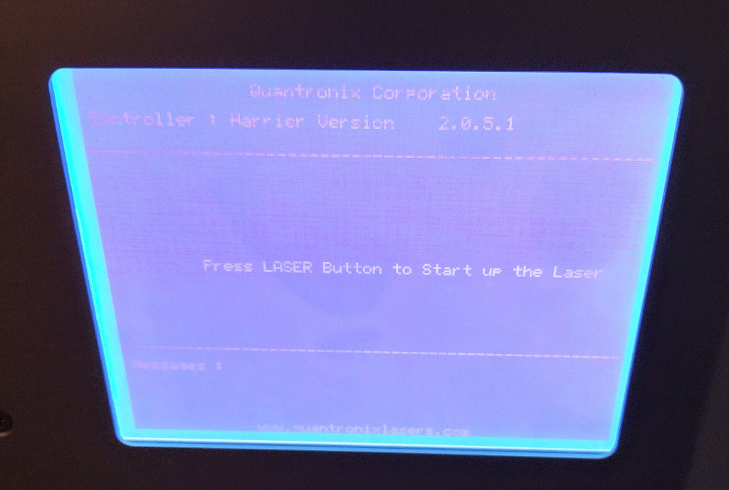
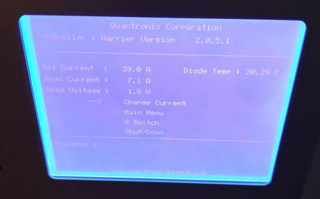
There was a little two-pin through-hole location on the PCB labeled “S1” for “switch one”, which wasn’t populated at all. There was no solder on the PCB like a component was removed or anything like that. It just wasn’t connected. So, I soldered in a little pin socket and made a jumper to close the circuit, turned things on and, there it was! Everything would power on now! I was getting all the needed voltages on the output rails, and the screen would turn on and display some output. Image of the controller screen after boot is shown below.
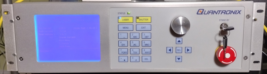
Now that the controller seemed to be booting up correctly, I needed to connect the laser head and see if it would work. The first step was to defeat the key switch. I do have a set of lock picks for just this kind of occasion, but figured I’d replace the switch since I was in the case anyway. To get started testing, I just cut the wires to the switch and twisted them together. This then allowed me to press the “LASER” button on the controller to get the laser head fired up. An image of the front panel of the controller follows (this image shows the new key switch installed).
 (Large Version)
However, this then presented another problem. The screen on the controller showed a diode temperature set point of 20°C, but the measured temperature was quickly dropping. It’s winter here, and the initial temperature of the diodes was under 20°C, so they should be heating up, not cooling down. After waiting a while, they were getting down to less than 8°C and still dropping, so I turned things off. This was a huge disappointment, as I had hoped things would be compatible and just work.
However, the observed behavior gave me an idea: if I could get the starting pump diode temperature to be over 20°C instead of under, then it might stop cooling when it hit 20°C. Even though the controller chilled the diodes down quite a lot, the thermo-electric cooler (TEC) / Peltier on the pump diodes is not very efficient. While one side gets very cold, the other gets hot, and the overall process generates heat. This made the bulky heatsink quite warm from all the work. Since I turned things off without letting the fan do a full shutdown and cool the heatsink back down, the heat from the large aluminum heatsink was then flowing back into the pump diodes and warming them up. This process was able to bring the pump diodes above 20°C.
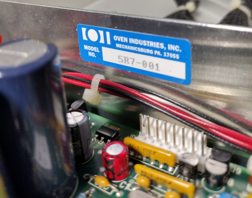
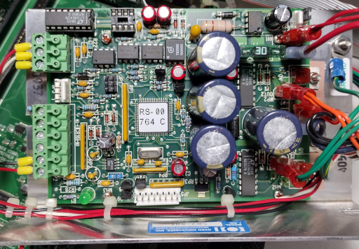
What actually happened when I waited for the pump diodes to warm up and started the controller again was quite informative. Instead of cooling the diodes like it was doing before, it was now quickly heating them up! I shutdown the controller immediately so I wouldn’t overheat the diodes. However, this was wonderful information. This means that the TEC does indeed work both directions, and the temperature sensors are fine; the TEC is probably just connected backwards. Inspired by this, I looked into the controller’s case yet again, this time taking a close look at the oven controller, a model 5R7-001 from Oven Industries Inc. located in Mechanicsburg, PA. The oven controller board is shown in the following images.
 (Large Version)
With the insight that the oven controller was probably connected backwards to the TEC on the 808nm pump diodes, I buzzed out the connections from the oven controller to the laser head. I could see that the two outputs from what I assumed was the oven controller did in fact go straight into the laser head, so switching them around at the connection point to the controller would be easy. I used the old Star Trek technique of “reversing the polarity” (I swapped the connections around), crossed my fingers, and hoped nothing would blow up when I turned things back on. I was absolutely thrilled when things started working perfectly!
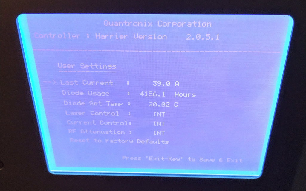
The laser would complete the startup sequence and maintain a stable temperature! All that was needed was to short the interlock pins on the back of the laser PSU, and I could finally enable the beam! A quick measurement with a cheap Chinese laser power meter showed that the laser was putting out 4W+. While the laser head was originally 20W, getting 4W out still seems fantastic. A 4W output should be plenty for some laser engraving, and there may be more that I can do to improve the output power as well. Some images from the controller’s screen accessible with the laser attached are shown below.
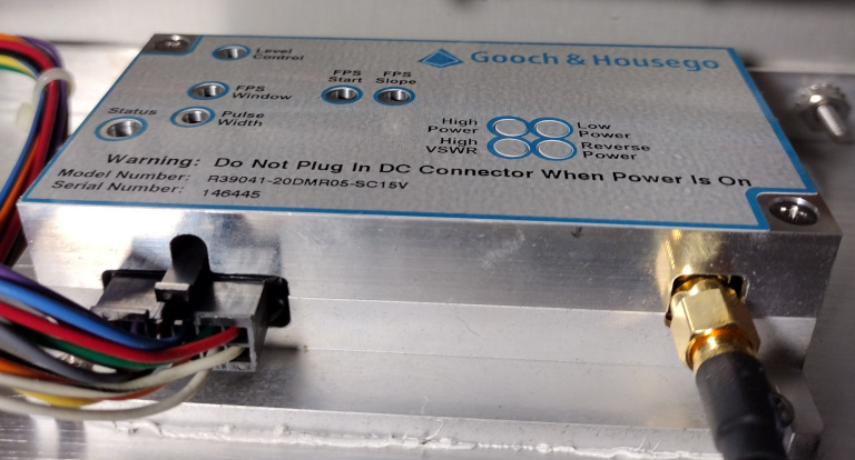
Finally, a couple more images from inside the PSU showing the Q-switch driver and the FPGA board follow. The Q-switch driver is a Gooch & Housego model R39041-20DMR05-SC15V, and the FPGA is an Altera Cyclone.
 (Large Version)
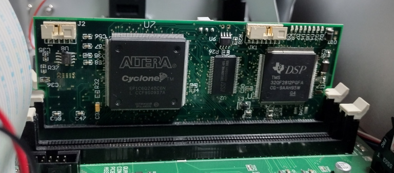 (Large Version)
Since the laser was only putting out about 4W @ 1064nm when powered on in CW mode, I wanted to get a quote for a repair from a professional repair company, just to see how much it would cost. TJS Lasers said they service this model, but wanted pictures of the inside of the laser cavity including the 808nm pump diode bar (and any markings) to confirm they would be able to work on it.
I was initially very hesitant to open the cavity, as even a small speck of dust on the optics in the resonator could cause damage. The dust can heat up and burn, damaging the optical coatings and cause the coatings to absorb the laser light. Then the damaged coating can heat up and spread damage further. This damage can then spread and result in total failure of the device, all from an initial little speck.
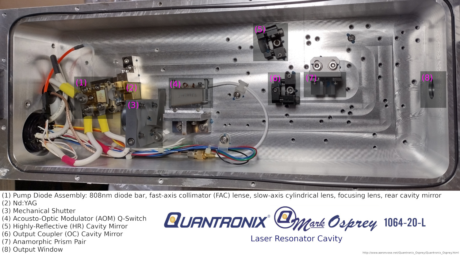
However, I couldn’t get a quote without the pictures of the pump assembly, and I was curious to see the inside of the Quantronix Osprey laser cavity, so I decided to risk it and open the case. I wanted pictures for this write up anyway. The images below show the inside of the laser resonator cavity.
The resonator takes the form of a V-shape, with the corner of the “V” placed on the left where the Nd:YAG is located (2). The upper arm of the “V” is terminated with a highly-reflective (HR) mirror in the upper right (5), while the bottom arm of the “V” ends at the output coupler (OC) mirror (6), after passing through the mechanical shutter (3) and acousto-optic modulator (AOM) Q-switch (4). Finally, the output beam goes through an anamorphic prism pair to clean up the beam shape and leaves the laser head via the protective output window (8). While the image labels the 808nm diode pump assembly (1) as using a mirror (S1:AR@808nm, S2:HR@1064nm) for the corner of the resonator cavity, it’s possible that this is just another lens, and the Nd:YAG crystal itself has the HR coating (I can’t tell without taking things apart to test them and don’t plan to do so).
 (Large Version)
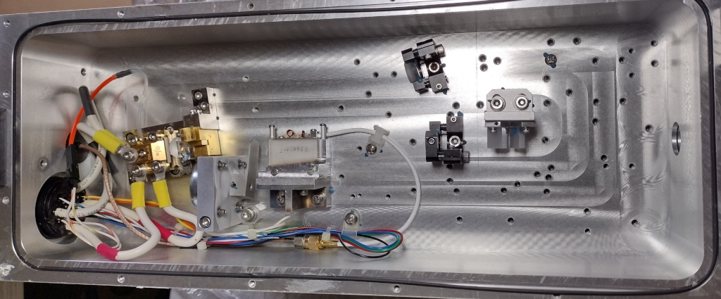 (Large Version)
Now that the laser situation was mostly worked out, I could start the process of figuring out how I was going to control the laser beam for engraving. I was inspired by a video I found on Les Wright’s YouTube channel, Les’ Lab. In this video, he shows how he was able to get a used CO2 laser and scan head working with an Arduino Teensy microcontroller. The key here is that the scan head speaks the XY2-100 protocol, which turns out to be an industry standard. You can find the surprisingly sparse specification document archived on my site in PDF format here.
There’s an open source project on GitHub called OPAL / OpenGalvo which provides firmware (FW) for the Arduino Teensy 4.0, enabling it to speak XY2-100 to the scan head to control the laser beam path. It also provides PWM output to control the laser intensity. The FW reads G-code input (G0 and G1 commands only) from a standard USB emulated serial connection, so one can write their own controller software for a PC in Python or something, or just use a Linux terminal to “cp” a G-code file to the appropriate TTY device file in “/dev” if one is lazy. Les also contributed a PCB design with Gerber files to the project and had a discount link to the PCB manufacturer JLCPCB (the discount link may not be active now, but the prices there are reasonable anyway). An image of the PCB design follows.
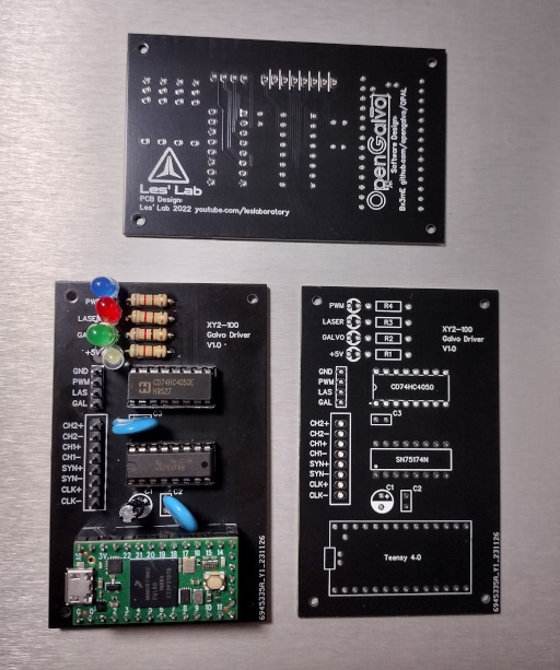 (Large Version)
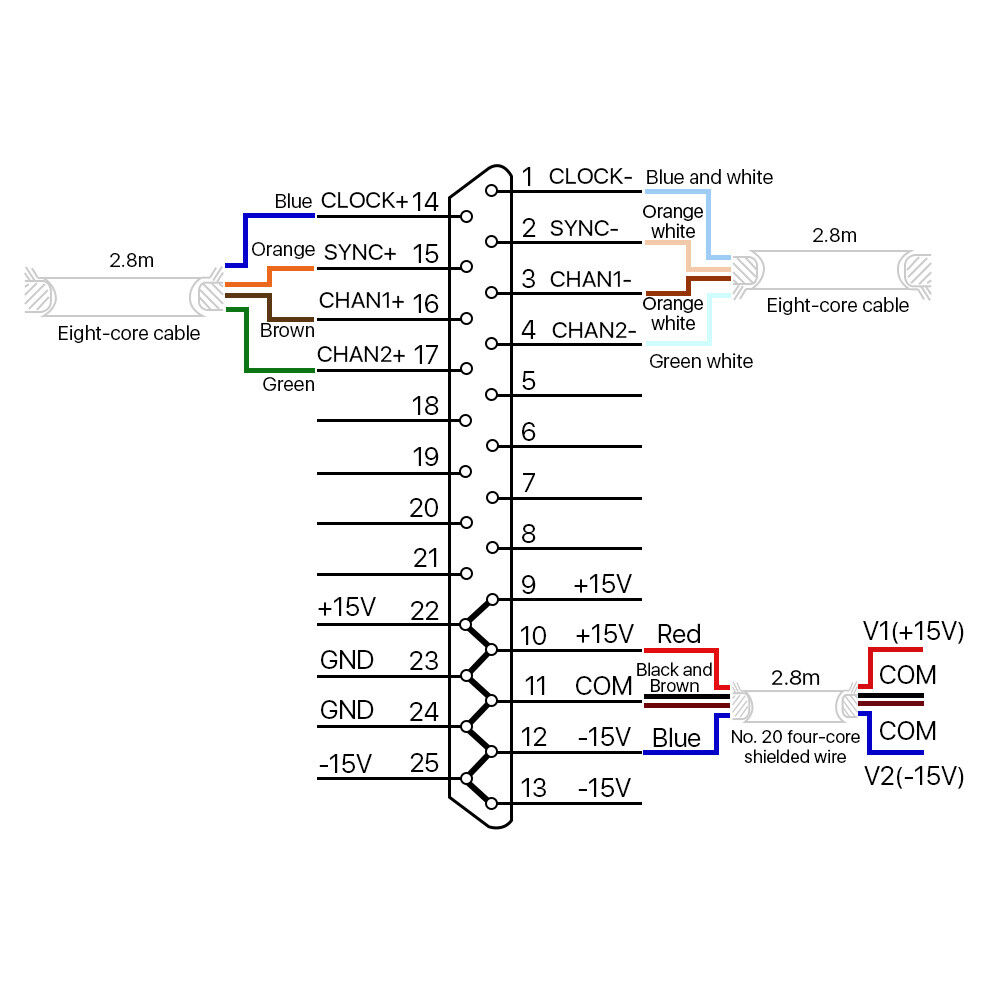
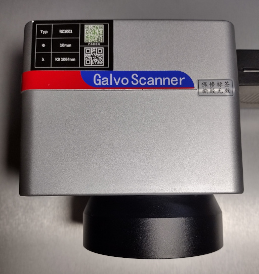
I purchased a Cloudray RC1001 galvanometer scan head on eBay; this was a little expensive at about $275 (in 2023). While I do have another scan head I extracted from a Domino CO2 laser much like Les did, the used scan head was built for the CO2 laser’s 10,600nm, while I needed a 1064nm model for the Osprey laser. I think the only significant difference here is in the reflective coatings on the mirrors. A wiring diagram for the DB25 port and some technical information on the Cloudray RC1001 follow.
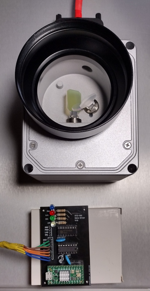
Some images of the galvanometer scan head follow.
A quick update here is that I finally got a scan head working and a completely functional laser engraving system setup, but unfortunately, it was not with the Quantronix Osprey laser. I haven’t yet figured out how to control the Osprey from a PWM perspective, so it’s not usable in an engraving system yet with the current always on / always off configuration via the PSU menu interface. -- However, I did get a system setup using a Domino CO2 laser, pretty much the same kind of a system as is shown in Les’ video. A full write-up of that project will have to wait for another day.
That said, I made some software for driving OPAL / OpenGalvo controllers which handles image to G-Code conversion as well as sending the G-Code commands over a serial interface to the contoller PCB. This project is written in Python, is open-source, and is available on my GitHub: OG-Code (Open G-Code).
OG-Code (Open G-Code) is a utility for working with G-code (Geometry Code) and has a focus on interoperability with the OpenGalvo (OPAL) project for laser engraving: https://github.com/opengalvo/OPAL. -- Combined, OpenGalvo and OG-Code provide a complete, end-to-end, open-source software solution for controlling laser engravers and cutters using galvanometer scan heads that support the XY2-100 protocol. -- Thanks to Les Wright of YouTube channel “Les’ Lab” for inspiration and advice. Les also provides an open-source PCB design customized to work with OpenGalvo: https://github.com/leswright1977/OPAL_PCB.

